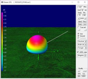
I’ve fooled around with an modeling program called 4nec2 a bit in the past (when I was simultaneously fooling around with an ADS-B receiver). Lately, I’ve been taking a more serious look at it to see if I can find ways to improve my outgoing HF signal from the EFHW-8010. If you look at the 3D radiation pattern, you can see that most of the power is being directed straight up (80 meter simulation). This is in spite of the fact that I have at least one of the ends pretty high. The model I created isn’t an exact replica, of course….in reality, the ground slopes down as the antenna slopes up, and there is a slight kink in the wire as it goes over a first tree on it’s way to the tall tree at the far end. But I’m pretty sure that the simulation results are in the right neighborhood. Maybe I should set up a second antenna: vertically in that same big tree. A vertical will concentrate more power at low angles, which should improve the performance. I would have to cut the length down (losing 80 meters), but it could be interesting……